Question Distribution & Your Strength
| Chapter | Marks Weightage | Your Proficiency |
|---|---|---|
| Electrostatics | 08 | Medium |
| Current Electricity | 07 | High |
| Magnetism & M.E.C. | 08 | Low |
| EM Induction & AC | 08 | Medium |
| Optics | 14 | High |
| Dual Nature & Modern Physics | 12 | Low |
| Communication Systems | 03 | Medium |
Source: CBSE Sample Paper & your latest mock results
Analytical Problem Solver
Electric Charges & Fields – Tough Spot
Problem Statement
Using Gauss’s theorem, derive the electric field \(E(r)\) at a distance \(r\) from an infinitely long straight wire with uniform linear charge density \( \lambda \).
Given:
- Infinite straight wire → cylindrical symmetry
- Uniform linear charge density \( \lambda \)
- Observation point at radial distance \( r \)
To Find:
Magnitude and direction of \( E(r) \) using Gauss theorem.
Solution Approaches
Cylindrical Gaussian Surface
Exploit symmetry; field constant on curved surface, zero through caps.
Line-element Integration
Integrate Coulomb’s law along wire; confirms \(E \propto 1/r\).
Dimensional Check
Verify units and \(1/r\) dependence for linear charge distributions.
Logical Breakdown
Symmetry
Infinite length ⇒ field radial, depends only on \(r\).
Gaussian Surface
Choose cylinder of radius \(r\) and length \(L\).
Flux Calculation
Flux \( \Phi = E(2\pi rL) \); caps contribute zero.
Gauss Theorem
Set \( \Phi = Q_{\text{enc}}/ \varepsilon_0 = \lambda L / \varepsilon_0\).
Step-by-Step Solution
Construct Gaussian Cylinder
Radius \(r\), length \(L\), axis along wire.
Evaluate Electric Flux
Caps perpendicular to field ⇒ no flux. Curved surface gives \( \Phi = E\,2\pi rL \).
Apply Gauss Theorem & Solve
Set \( E\,2\pi rL = \lambda L/\varepsilon_0 \) ⇒ \( E(r) = \dfrac{\lambda}{2\pi \varepsilon_0 r} \) radially outward.
Key Insights
-
Gauss theorem turns a difficult integral into one line when symmetry exists.
-
For linear charge distributions, \(E \propto 1/r\), not \(1/r^{2}\).
-
Exclude end-caps in flux; including them doubles the result—common error.
Moving Charges & Magnetism – Radius Change
CBSE Grade 12 • Physics
Problem Context
An electron moves in a uniform magnetic field \( \mathbf{B} \). It describes a circle of radius \( r_0 \) with period \( T_0 \). Its speed is suddenly doubled to \( 2v_0 \).
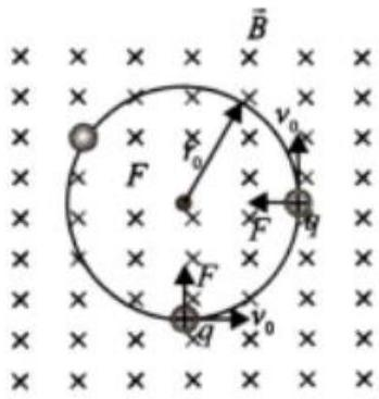
Question
After the speed doubles, calculate the new orbit radius \( r \) and time period \( T \).
a) Radius \( r=? \)
b) Period \( T=? \)
Helpful Hints
Hint 1
\( r=\frac{mv}{qB} \); radius is proportional to speed.
Hint 2
Cyclotron period \( T=\frac{2\pi m}{qB} \) is independent of speed.
Hint 3
Doubling \( v \) ⇒ \( r=2r_0 \) while \( T \) remains \( T_0 \).
Things to Consider
- Lorentz force \( q\mathbf{v}\times\mathbf{B} \) only changes direction, not speed.
- Cyclotron period depends only on \( m, q, B \).
- Avoid assuming period varies with velocity.
Related Concepts
Analytical Problem Solver
Alternating Current – LCR Surprise
Problem Statement
A series LCR circuit has \(V_R = V_L = V_C = 10\text{ V}\) at the supply frequency. If the capacitor is short-circuited, determine the new voltage across the inductor.
Given:
- Series LCR at resonance ⇒ \(V_L = V_C\) and supply \(V = V_R\).
- \(V_R = V_L = 10\text{ V}\).
- Frequency unchanged; hence \(X_L\) stays same after change.
To Find:
Voltage \(V_L'\) across the inductor after the capacitor is shorted.
Solution Approaches
Phasor Method
Use phasor triangle: find new current with \(Z_{RL}\) then compute \(V_L' = I'X_L\).
Impedance Calculation
Treat circuit as RL series: \(Z = \sqrt{R^{2}+X_L^{2}}\); derive \(I'\) from Ohm’s law.
Qualitative Reasoning
Recognise that removing \(X_C\) raises impedance by \(\sqrt{2}\); hence current and \(V_L\) fall by \(\sqrt{2}\).
Logical Breakdown
Resonant Baseline
At resonance: \(I = V/R\) and \(X_L = R\).
Reactance Relationships
With \(X_C\) removed, only \(X_L\) opposes \(R\).
New Impedance
\(Z_{RL} = \sqrt{R^{2}+X_L^{2}} = R\sqrt{2}\).
Current Adjustment
\(I' = V/Z_{RL} = I/\sqrt{2}\).
Step-by-Step Solution
Find \(R\) and \(X_L\)
Equal voltages give \(R = X_L\).
Compute New Current
After shorting \(C\): \(Z_{RL}=R\sqrt{2}\).
Voltage Across \(L\)
\(V_L' = I'X_L = \dfrac{10}{\sqrt{2}}\text{ V} \approx 7.1\text{ V}\).
Key Insights
-
At resonance, reactive voltages cancel but each can exceed supply voltage.
-
Removing the capacitor raises impedance by \(\sqrt{2}\) in a series RL network.
-
Phasor relations let us quickly recalculate voltages after circuit changes.
Analytical Problem Solver
Wave Optics – First Common Dark Fringe
Problem Statement
In Young’s double-slit experiment, two monochromatic beams of wavelengths \( \lambda_1 = 400\,\text{nm}\) and \( \lambda_2 = 600\,\text{nm}\) illuminate the same slits. Find the smallest distance \(y\) from the central maximum where both wavelengths produce a dark fringe simultaneously.
Given:
- Young’s double-slit set-up (YDS)
- \( \lambda_1 = 400\,\text{nm},\; \lambda_2 = 600\,\text{nm}\)
- Slit separation \(d\) and screen distance \(D\)
To Find:
Nearest common dark-fringe position \(y\) (express in \(D\) and \(d\)).
Solution Approaches
Path-difference Equality
Set a single \( \delta\) satisfying dark-fringe conditions for both wavelengths and solve for \(y\).
Fringe-width LCM
Find the lowest common multiple of individual dark-fringe spacings.
Graphical Intersection
Plot minima positions for each colour and read the first overlap.
Logical Breakdown
YDS Geometry
Path difference \( \delta = \dfrac{d\,y}{D}\).
Dark-Fringe Rule
Minima when \( \delta = (n+\tfrac12)\lambda\).
Common Condition
Set \( (n_1+\tfrac12)\lambda_1 = (n_2+\tfrac12)\lambda_2\).
Convert to \(y\)
Use \( y = \delta D / d \) or \( y = \dfrac{\delta}{\lambda}\beta\).
Step-by-Step Solution
Set Equality
Let integer \(m\) satisfy \( m\lambda_2 = (m+\tfrac12)\lambda_1\).
Solve for \(m\)
Substitute values to get \( m = 1\).
Find \(y\)
Path difference \( \delta = m\lambda_2 = 600\,\text{nm}\). Hence \( y = \dfrac{600\,\text{nm}\,D}{d}\).
Key Insights
-
Common dark fringes satisfy one shared path difference across both wavelengths.
-
The condition converts to a simple integer equation in \(m\).
-
Result: \( y = \dfrac{600\,\text{nm}\,D}{d}\); independent of chosen integer once minimal.
Analytical Problem Solver
Nuclei – Fission vs Fusion
Problem Statement
Using the B.E./A curve, predict which of the nuclei W (190), X (90), Y (60) and Z (30) are likely to undergo fission or fusion. Give qualitative reasons.
Given:
- B.E./A peaks near mass number A ≈ 56.
- Higher binding energy per nucleon implies greater nuclear stability.
- Energy is released when total binding energy increases.
To Find:
Process (fission/fusion) favoured by each nucleus based on nuclear stability.
Solution Approaches
Read B.E./A Trend
Locate each mass number relative to the 56-peak.
Apply Stability Rule
For A > 56, fission raises B.E./A; for A < 56, fusion does.
Compute Energy Gain
Estimate \( \Delta E \) from change in total binding energy.
Logical Breakdown
Binding-Energy Peak
Maximum stability at A ≈ 56 (Fe, Ni).
Heavy Nuclei (A > 56)
Lower B.E./A; splitting raises stability → fission.
Light Nuclei (A < 56)
Lower B.E./A; combining raises stability → fusion.
Energy Criterion
\( \Delta E \propto \Delta(\text{B.E.}/A)\,A \); positive ΔE means feasible.
Step-by-Step Solution
Locate on Curve
W 190, X 90 → far right of peak; Y 60 → near peak; Z 30 → left of peak.
Apply Rule
A > 56 → fission favoured; A < 56 → fusion favoured; near-peak gives negligible gain.
State Outcome
• W 190 & X 90: fission increases binding energy.
• Z 30: fusion increases binding energy.
• Y 60: almost no change, so neither strongly favoured.
Key Insights
-
Binding-energy per nucleon curve predicts nuclear processes at a glance.
-
Raising B.E./A drives reactions toward greater nuclear stability.
-
Interpretation skill meets the learning outcome: decide fission vs fusion qualitatively.
Electrostatic Potential & Capacitance – Inserting Slabs
Grade 12 Physics
Problem Statement
A parallel-plate capacitor (area \(A\), gap \(d\)) receives a central slab of thickness \(t<d\). (i) The slab is dielectric of constant \(\kappa\). (ii) The slab is metallic. Derive the new capacitance in each case and state which configuration gives the larger value.
Given:
- Plate area \(A\)
- Plate separation \(d\)
- Inserted slab thickness \(t\) (\(t<d\))
- Dielectric constant \(\kappa\) (case i)
To Find:
Capacitance \(C_d\) (dielectric), \(C_m\) (metal) and compare.
Solution Approaches
Series-capacitor model
Treat air gaps and slab as capacitors in series.
Energy comparison
Minimise stored energy for given charge.
Field mapping
Analyse uniform fields in each region.
Logical Breakdown
1. Series capacitors
Air gaps and slab share charge; voltages add.
2. Dielectric effect
Field weakens inside slab by factor \(\kappa\).
3. Metallic slab
Acts as equipotential; eliminates \(t\) from gap.
4. Comparison
Smaller effective separation ⇒ larger capacitance.
Step-by-Step Solution
Derive \(C_d\) (dielectric)
Two air gaps of \((d-t)/2\) each and one dielectric slab form three capacitors in series.
Derive \(C_m\) (metal)
Metallic slab becomes part of the plates; effective separation reduces to \(d-t\).
Compare
Since \(\kappa>1\), \(d-t<d-t+\dfrac{t}{\kappa}\) ⇒ \(C_m>C_d>C_0\).
Key Insights
-
Capacitance rises when effective plate gap falls.
-
Dielectric insertion requires series-capacitor treatment, not parallel.
-
Metal slab gives greater increase than any dielectric with finite \(\kappa\).
Analytical Problem Solver
Electromagnetic Waves – Displacement Current
Problem Statement
A \(0.001\ \text{m}^2\) parallel-plate capacitor, plate gap \(d = 10^{-4}\ \text{m}\), is charged so that \(\frac{dV}{dt}=1\times10^{8}\ \text{V s}^{-1}\). Find the displacement current between the plates.
Given:
- Area \(A = 0.001\ \text{m}^2\)
- Separation \(d = 10^{-4}\ \text{m}\)
- \(\frac{dV}{dt}=1\times10^{8}\ \text{V s}^{-1}\)
- \(\varepsilon_0 = 8.85\times10^{-12}\ \text{F m}^{-1}\)
To Find:
Displacement current \(I_d\) using Ampere-Maxwell law.
Solution Approaches
Direct formula
Use \(I_d=\varepsilon_0 A\,\frac{dE}{dt}\) with \(E=V/d\).
Ampere-Maxwell loop
Apply \(\oint \mathbf{B}\cdot d\mathbf{l}=\mu_0(I_c+I_d)\) with \(I_c=0\).
Energy method
Relate rate of change of stored energy to equivalent current.
Logical Breakdown
Displacement current idea
Time-varying electric field inside a capacitor acts like a current in Ampere-Maxwell law.
Field–voltage link
\(E=\frac{V}{d}\) for uniform field between plates.
Rate of change
\(\frac{dE}{dt}=\frac{1}{d}\frac{dV}{dt}\).
Compute \(I_d\)
Insert values in \(I_d=\varepsilon_0 A\,\frac{dE}{dt}\).
Step-by-Step Solution
Relate \(E\) and \(V\)
\(E=\frac{V}{d}\) ⇒ \(\frac{dE}{dt}=\frac{1}{d}\frac{dV}{dt}\).
Apply displacement current formula
\(I_d=\varepsilon_0 A\,\frac{dE}{dt}\).
Numerical value
Compute the product.
Key Insights
-
Displacement current replaces missing conduction current in capacitors.
-
Ampere-Maxwell law unifies magnetic effects of both conduction and displacement currents.
-
Mastering this link lets you apply Maxwell’s correction inside any time-varying dielectric region.
Analytical Problem Solver
Dual Nature – Photoelectron Wavelength
Problem Statement
A platinum surface (\( \phi = 5.63\,\text{eV} \)) is illuminated with light of frequency \( \nu = 1.6 \times 10^{15}\,\text{Hz} \). Determine the minimum de Broglie wavelength of the emitted photoelectrons.
Given:
- Planck constant \( h = 6.63 \times 10^{-34}\,\text{J s} \)
- Electron mass \( m_e = 9.11 \times 10^{-31}\,\text{kg} \)
- \( 1\,\text{eV} = 1.6 \times 10^{-19}\,\text{J} \)
To Find:
Shortest de Broglie wavelength \( \lambda_{\min} \) of photoelectrons
Solution Approaches
Photoelectric Equation
Apply \( h\nu = \phi + K_{\max} \) to find electron kinetic energy.
Consistent Units
Convert \(\phi\) and \(K_{\max}\) from eV to joule.
Matter-Wave Relation
Use \( \lambda = \frac{h}{\sqrt{2m_e K_{\max}}} \) to compute \( \lambda_{\min} \).
Logical Breakdown
Photon Energy
Calculate \( E = h\nu \).
Work Function
Energy needed to free an electron: \( \phi \).
Kinetic Energy
\( K_{\max} = E - \phi \).
de Broglie Wavelength
\( \lambda = \frac{h}{\sqrt{2m_e K_{\max}}} \).
Step-by-Step Solution
Photon energy
\( E = h\nu = 6.63 \times 10^{-34}\,\text{J s} \times 1.6 \times 10^{15}\,\text{Hz} = 1.06 \times 10^{-18}\,\text{J} \)
Maximum kinetic energy
\( \phi = 5.63\,\text{eV} = 9.01 \times 10^{-19}\,\text{J} \)
\( K_{\max} = E - \phi = 1.06 \times 10^{-18} - 9.01 \times 10^{-19} = 1.59 \times 10^{-19}\,\text{J} \)
de Broglie wavelength
\( \lambda = \frac{h}{\sqrt{2m_e K_{\max}}} = \frac{6.63 \times 10^{-34}}{\sqrt{2 (9.11 \times 10^{-31})(1.59 \times 10^{-19})}} \approx 1.2 \times 10^{-9}\,\text{m} \)
Key Insights
-
Photon energy beyond the work function converts to electron kinetic energy.
-
Kinetic energy sets momentum, linking photoelectric effect to matter waves.
-
Understanding this link satisfies the learning outcome: relate photon energy to de Broglie wavelength.
Semiconductor Electronics – Rectifier & Filter
Identify stages that convert AC to smooth DC.
Problem Statement
In the chain AC → X → Y → load, name X and Y, and illustrate their output waveforms.
Given:
- Input: sinusoidal AC mains.
- X contains p–n junction diodes (rectification).
- Y uses RC/LC network (filter circuit).
To Find:
Stage names and corresponding waveforms at outputs of X and Y.
Solution Approaches
Half-wave rectifier + RC filter
Identify X as single-diode rectifier; Y as capacitor across load.
Bridge rectifier + π-filter
Use four-diode bridge for full-wave pulses; π (C-L-C) smooths further.
Compare ripple levels
Evaluate reduction from X to Y to validate correct identification.
Logical Breakdown
Diode Rectification
Diode permits current one way, producing pulsating DC from AC.
Half vs Full Wave
Full-wave doubles pulse frequency, reducing initial ripple.
Filter Circuits
Capacitor stores charge; inductor resists change, smoothing voltage.
Ripple Reduction
Proper RC/LC choice lowers \(r\) without altering frequency.
Step-by-Step Solution
Identify X
X is the rectifier: half-wave (one diode) or full-wave (bridge/center-tap).
Identify Y
Y is the filter circuit: RC, LC or π-section that smooths the pulsating DC.
Sketch Waveforms
Draw half/full-wave pulses at X; add capacitor-charged peaks to show smooth line at Y.
Key Insights
-
Rectifier (X) turns AC into unidirectional pulses using diodes.
-
Filter (Y) employs capacitors/inductors to cut ripple, not frequency.
-
Avoid calling the filter a regulator; regulation is a separate stage.
Analytical Problem Solver
Current Electricity – Heating Element Analysis
Problem Statement
A heater connected to a 100 V battery with internal resistance 1 Ω draws 10 A at 20 °C. After heating to 320 °C the current stabilises lower. Find the power lost inside the battery at the final temperature.
Given:
- Supply voltage \(V = 100 \text{ V}\)
- Internal resistance \(r = 1 \,\Omega\)
- Initial current \(I_0 = 10 \text{ A at }20^{\circ}\text{C}\)
- Final temperature \(T = 320^{\circ}\text{C}\)
- Temperature coefficient \(\alpha = 3.7\times10^{-4}\,^{\circ}\text{C}^{-1}\)
To Find:
Power dissipated in the battery’s internal resistance at 320 °C.
Solution Approaches
Direct α-based Calculation
Find heater resistance at 20 °C, scale it with \(R_T = R_0(1+\alpha\Delta T)\), then compute current and \(P = I^2 r\).
Ratio Method
Use \(I_T/I_0 = 1/\big(1+\alpha\Delta T\big)\) to get current directly, then evaluate \(P = I_T^{2} r\).
Graphical Insight
Plot \(R\) versus \(T\) to visualise how the temperature coefficient influences current and power loss.
Logical Breakdown
Initial Heater Resistance
\(R_0 = \frac{V}{I_0} - r\)
Temperature Coefficient Role
Resistance rises linearly with \(\alpha\Delta T\).
Current at 320 °C
Use \(I_T = V /(R_T + r)\).
Power Loss Inside Battery
Calculate \(P = I_T^{2} r\).
Step-by-Step Solution
Find \(R_0\)
\(R_0 = \frac{100}{10} - 1 = 9\,\Omega\).
Compute \(R_T\)
\(\Delta T = 300^{\circ}\text{C}\); \(R_T = 9[1 + (3.7\times10^{-4})(300)] \approx 10\,\Omega\).
Evaluate \(I_T\) and \(P_{batt}\)
Total resistance \(= 10 + 1 = 11\,\Omega\); \(I_T = 100/11 \approx 9.09 \text{ A}\). Power loss \(P_{batt} = (9.09)^2 \times 1 \approx 83 \text{ W}\).
Key Insights
-
Temperature coefficient raises heater resistance, lowering current.
-
Internal power loss is governed by \(I^{2} r\), not by battery voltage directly.
-
Accounting for temperature-dependent resistance prevents under-estimating power loss in circuits.
Analytical Problem Solver
Electromagnetic Induction – AC Generator Emf
Problem Statement
Derive the instantaneous emf \( \varepsilon(t) \) of an \( N \)-turn coil of area \( A \) rotating with angular speed \( \omega \) in a uniform magnetic field \( B \).
Given:
- Generator principle: rotating coil cuts magnetic flux.
- Uniform field \( B \); coil area \( A \); turns \( N \).
- Angular speed \( \omega \); initial angle \( \theta_0 = 0 \).
To Find:
Expression \( \varepsilon(t) = \varepsilon_0 \sin \omega t \) where \( \varepsilon_0 = N B A \omega \).
Solution Approaches
Flux–Derivative Method
Write magnetic flux, differentiate using Faraday’s law.
Phasor View
Treat flux as rotating vector; emf is its vertical component.
Energy Perspective
Relate mechanical power \( \tau \omega \) to electrical power \( \varepsilon I \).
Logical Breakdown
Generator Principle
Rotation converts mechanical work into emf via changing flux.
Magnetic Flux
\(\Phi = N B A \cos \theta\).
Rotational Emf
Time-varying angle \( \theta = \omega t \) gives sinusoidal flux.
Sign & Phase
Negative sign sets phase; dropping it shifts waveform by \( \pi \).
Step-by-Step Solution
Write Flux
Angle between \( \mathbf{B} \) and normal is \( \theta = \omega t \).
Apply Faraday’s Law
Induced emf equals negative rate of change of flux.
Differentiate & Simplify
Derivative of cosine gives sine; amplitude is \( N B A \omega \).
Key Insights
-
Sinusoidal emf emerges directly from rotational motion plus Faraday’s law.
-
Amplitude \( \varepsilon_0 = N B A \omega \) scales with turns, field, area, and speed.
-
Correct sign ensures correct phase; dropping it shifts the waveform by 180°.
Ray Optics – Cassegrain Telescope
CBSE Grade 12 Physics
Problem Statement
Draw a neat ray diagram of a Cassegrain reflecting telescope and state any two reasons it outperforms a similar-sized refracting telescope.
Given:
- Primary concave parabolic mirror with central hole
- Secondary small convex mirror facing the primary
- Eyepiece placed behind the primary mirror
To Find:
Complete ray path and two performance advantages (compact length, zero chromatic aberration).
Solution Approaches
Trace Rays
Show two reflections and final focus at eyepiece.
Identify Components
Label mirrors, focal points and central hole.
Compare Designs
List reflector advantages over refractor.
Logical Breakdown
Optical Path
Parallel light → primary mirror → convex secondary → through central hole → eyepiece.
Tube Length
Folded path gives long focal length inside a short, manageable tube.
Aberrations
All-mirror system removes chromatic dispersion found in lenses.
Common Errors
Eyepiece must be behind primary; include hole in primary mirror.
Step-by-Step Solution
Sketch Mirrors
Draw large concave primary (with hole) and small convex secondary near its focus.
Trace Incident Rays
Show parallel rays reflecting at primary, converging to secondary, then passing through hole to focus.
Note Advantages
Write: (i) No chromatic aberration (ii) Large aperture with compact length.
Key Insights
-
Reflection is wavelength-independent → no chromatic aberration.
-
Large parabolic mirror gathers more light than an equal-diameter lens and is lighter.
-
Secondary mirror folds path, giving long focal length in a short tube.
Analytical Problem Solver
Atoms – Many Lines, One Electron
Problem Statement
Hydrogen has only one electron, yet its emission spectrum shows many lines. Explain why.
Given:
- Sample contains about \(10^{23}\) hydrogen atoms.
- Collisions excite electrons to various Bohr energy levels.
- Bohr model allows discrete electron transitions.
To Find:
Reason for multiple spectral lines from a one-electron atom.
Solution Approaches
Many Atoms, Many States
Large ensemble ensures electrons occupy several excited levels simultaneously.
Cascade Transitions
Each electron can drop through several energy gaps, emitting photons of different energies.
Bohr Quantisation
Energy difference \(E_{n_i}-E_{n_f}=h\nu\) sets a unique wavelength for every allowed pair \((n_i,n_f)\).
Logical Breakdown
1 . Ensemble Size
Different atoms act independently, adding their emissions.
2 . Excitation
Collisions lift electrons to \(n>1\) states.
3 . Multiple Drops
Each excited electron can follow many downward paths.
4 . Distinct Energies
Energy gaps differ, so photons have different wavelengths.
Step-by-Step Solution
Quantised Energies
Bohr gives \(E_n=-13.6\,\text{eV}/n^2\).
Population of Levels
Thermal or electrical collisions move electrons to higher \(n\).
Emission of Photons
When an electron drops from \(n_i\) to \(n_f\), photon energy \(h\nu = E_{n_i}-E_{n_f}\).
Key Insights
-
Multiple atoms and levels create a rich emission spectrum.
-
Each Bohr transition yields one precise wavelength.
-
Mistakes: blaming extra electrons or forgetting ensemble effects.
Key Take-aways
Formula Vault
Recap core equations: \(v=u+at\), \(F=q(E+v\times B)\), lens & capacitor rules for instant recall.
Units & Constants
Write \(c, h, e\) values on rough sheet. Convert units before substitution to avoid negative marking.
Strategic Scan
Read twice, underline data, decide concept, then pick a formula. This strategy cuts re-work.
Time Tactics
60 min theory, 30 min numericals, 10 min review. Skip tough items and return—classic time-saving tip.
Neat Work
Box answers, show steps, draw labelled diagrams. Presentation secures method marks.
Final Review
Things to remember: tally sub-parts, check sig-figs, use elimination for MCQs in the last sweep.