Question Distribution & Your Strength
| Chapter | Marks % | No. of Qns | Your Mastery |
|---|---|---|---|
| Electrostatics | 7 % | 4 | High |
| Current Electricity | 8 % | 5 | Medium |
| Magnetic Effects & Magnetism | 6 % | 3 | Low |
| EM Induction & AC | 8 % | 5 | Medium |
| Optics | 14 % | 9 | High |
| Modern Physics | 12 % | 7 | Low |
Source: CBSE Sample Question Paper (2024-25) & your last three mock tests
Analytical Problem Solver
Electric Charges & Fields – Q28 (I)
Problem Statement
Using Gauss’s law, derive the electric field \(E(r)\) at a distance \(r\) from an infinitely long straight wire of uniform linear charge density \( \lambda \).
Given:
- Infinite straight wire, charge density \( \lambda \).
- Point of observation at radius \( r \).
- Permittivity of free space \( \varepsilon_0 \).
To Find:
\(E(r)=\dfrac{\lambda}{2\pi\varepsilon_0 r}\)
Solution Approaches
Gauss Cylinder (Preferred)
Exploit cylindrical symmetry; apply Gauss’s law directly.
Direct Coulomb Integration
Integrate elemental fields; calculus-heavy.
Field-Line Argument
Use \(1/r\) spread of lines; needs Gauss verification.
Logical Breakdown
Symmetry Analysis
Infinite line ⇒ cylindrical symmetry around axis.
Gaussian Surface
Choose coaxial cylinder length \(L\), radius \(r\).
Flux Evaluation
Field radial & uniform on curved side; zero on ends.
Apply Gauss’s Law
Relate flux to enclosed charge \( \lambda L \) to get \(E\).
Step-by-Step Solution
Choose Gaussian Cylinder
Radius \(r\), length \(L\), coaxial with wire.
Compute Electric Flux
End-caps contribute zero; field constant on side.
Apply Gauss & Solve
Set \( \Phi = \dfrac{\lambda L}{\varepsilon_0} \) ⇒ isolate \(E\).
Key Insights
-
Electric field of a line charge follows \(E\propto1/r\) — a core result in Electric Charges and Fields.
-
End-cap flux vanishes because field lines are radial, not axial.
-
Picking the right Gaussian surface turns a 3-D integral into one line of algebra.
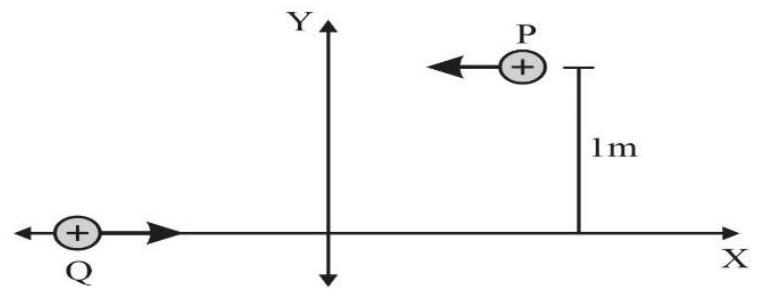
Moving Charges & Magnetism – Collision Setup
Q19 Head-on Collision of Two Charges
Two identical \(+4.8\times10^{-19}\,\text{C}\) particles start 0.5 m either side of the Y-axis, each with velocity \(2.4\times10^{5}\,\text{m\,s}^{-1}\) along \(-X\). A uniform magnetic field is applied so the particles bend and collide at the origin. Determine (i) the field direction, (ii) its magnitude.
Hints
- \(qvB = \frac{mv^{2}}{r}\); here \(r = 0.5\,\text{m}\).
- Right-hand rule: velocity \(-X\) crossed with \(\vec B\) gives magnetic force toward +Y.
- Equal radii create mirror paths, ensuring a head-on meeting.
Common mistakes
- Using the left-hand rule meant for negative charges.
- Treating 0.5 m as the diameter instead of the radius of curvature.
Analytical Problem Solver
Alternating Current – LCR Twist | Q6
Problem Statement
In a resonant series LCR circuit the measured drops are \(V_R = V_C = V_L = 10\,\text{V}\). After the capacitor is short-circuited, determine the new voltage across the inductor.
Given:
- Alternating current, steady state.
- Resonance: \(X_L = X_C\), supply frequency unchanged.
- Measured \(V_R = V_C = V_L = 10\,\text{V}\).
To Find:
Voltage \(V_L'\) across the inductor after the capacitor is removed.
Solution Approaches
Phasor & Resonance
Use \(V_s = V_R\) at resonance to get current \(I_0\) and relate \(R\) with \(ωL\).
Impedance Triangle
Treat the remaining RL series circuit, compute \(Z\) and new current to obtain \(V_L'\).
Check Pitfalls
Verify phase change; avoid assuming \(V_L\) remains 10 V after resonance is broken.
Logical Breakdown
1 Resonance Fact
At resonance \(V_s = V_R\); reactive voltages cancel.
2 Find R vs ωL
Given \(V_L = I_0 ωL\) and \(V_R = I_0 R\) ⇒ \(ωL = R\).
3 New Impedance
With capacitor shorted, \(Z = \sqrt{R^2 + (ωL)^2} = R\sqrt{2}\).
4 Compute VL'
Current drops to \(I_0/√2\); \(V_L' = (I_0/√2) ωL = 10/√2\).
Step-by-Step Solution
Determine \(V_s\) and \(I_0\)
Resonance ⇒ \(V_s = V_R = 10\,\text{V}\); current \(I_0 = 10/R\).
Relate \(R\) and \(ωL\)
Given \(V_L = I_0 ωL = 10\,\text{V}\), so \(ωL = R\).
Find \(V_L'\)
RL impedance \(Z = R√2\); current \(I = I_0/√2\); therefore \(V_L' = 10/√2 ≈ 7.1 V\).
Key Insights
-
Resonance pins supply voltage to the resistive branch only.
-
Removing a reactive element changes current and redistributes AC voltages.
-
Here \(V_L\) falls by \(1/√2\), illustrating voltage sharing in an RL circuit.
Analytical Problem Solver
Wave Optics – Dual-Wavelength Fringe
Problem Statement
Two monochromatic beams of wavelengths \( \lambda_1 = 400\,\text{nm} \) and \( \lambda_2 = 600\,\text{nm} \) illuminate a Young’s double-slit arrangement. Find the shortest distance from the central bright fringe where the screen is dark.
Given:
- Wavelengths \( \lambda_1 = 400\,\text{nm},\; \lambda_2 = 600\,\text{nm} \)
- Slit separation \( d \) and screen distance \( D \)
- Path difference on screen \( \Delta = \dfrac{y d}{D} \)
To Find:
Minimum distance \( y_{\text{min}} \) for a composite dark fringe.
Solution Approaches
Integer-condition method
Use \( m\lambda_2 = (m+\tfrac12)\lambda_1 \) to locate the first valid order.
LCM / beat-fringe idea
Find the least common path difference producing opposite phase for the two colours.
Graphical envelope
Plot individual intensity patterns and read the first common minimum.
Logical Breakdown
Interference basics
In Young’s double slit, \( \Delta = y d / D \).
Composite darkness
Need one wavelength an integral multiple and the other a half-integral multiple of \( \Delta \).
Diophantine solution
Solve \( m\lambda_2 = (m+\tfrac12)\lambda_1 \) for the least positive integer \( m \).
Distance on screen
Convert obtained \( \Delta \) into \( y_{\text{min}} \) via fringe width \( \beta = \lambda D/d \).
Step-by-Step Solution
Write combined condition
For first dark overlap: \( m\lambda_2 = (m+\tfrac12)\lambda_1 \).
Solve for the least \( m \)
With \( \lambda_1 = 400\,\text{nm}, \lambda_2 = 600\,\text{nm} \) we get \( m = 1 \) and \( \Delta = m\lambda_2 = 600\,\text{nm} \).
Translate to screen distance
\( y_{\text{min}} = \dfrac{\Delta D}{d} = \dfrac{600\,\text{nm}\,D}{d} = \dfrac32 \beta_1 = \beta_2 \).
Key Insights
-
Composite dark fringes need opposite-phase contributions from the two colours.
-
Search the smallest integer order; avoid assuming identical fringe numbers.
-
Express the answer in terms of fringe width \( \beta \) when geometry constants are unknown.
Nuclei – Binding-Energy Insights
Q20 Interpreting B.E./A Curve
Graph of binding energy per nucleon for nuclei W, X, Y and Z is shown.
(i) Which nucleus will release nuclear energy by fission?
(ii) Which nucleus will release nuclear energy by fusion?
Justify using the change in B.E./A.
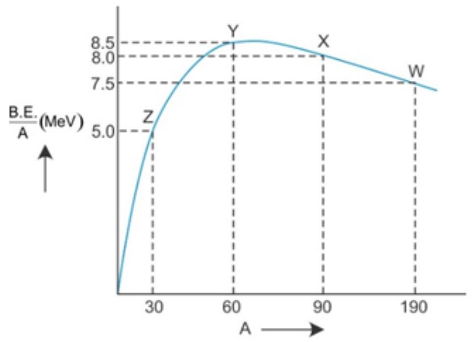
Hints:
- Higher B.E./A means greater nuclear stability.
- Heavy nucleus W (A ≈ 190) lowers its B.E./A by splitting → favours fission.
- Light nucleus Z (A ≈ 30) raises its B.E./A by merging → favours fusion.
- Energy gain stops near the iron peak; that energy appears as nuclear energy.
Common pitfalls: selecting by absolute B.E. only, or forgetting fusion is profitable only up to Fe.
Analytical Problem Solver
Electrostatic Potential & Capacitance
Problem Statement
A parallel-plate capacitor has plate area \(A\) and separation \(d\).
(a) A dielectric slab of thickness \(t\,(t<d)\) and relative permittivity \(k\) fills part of the gap.
(b) The slab is replaced by a metal of the same thickness \(t\).
Derive \(C_{\text{dielectric}}\) and \(C_{\text{metal}}\). State which case yields the larger capacitance.
Given:
- Plate area \(A\)
- Gap \(d\)
- Slab thickness \(t\,(t<d)\)
- Dielectric constant \(k\); vacuum permittivity \(\varepsilon_0\)
To Find:
Expressions for \(C_{\text{dielectric}}\) and \(C_{\text{metal}}\); compare magnitudes.
Solution Approaches
Series-Capacitor Model
Treat filled and empty regions as capacitors in series; compute effective separation.
Field-Potential Integration
Integrate \(E\) across each region to find total potential difference.
Limit Comparison
Compare formulas for \(t=0\) and \(t=d\) to validate results.
Logical Breakdown
Region Identification
Air gap of length \(d-t\); slab of length \(t\).
Individual Capacitances
\(C_1=\frac{\varepsilon_0 A}{d-t}\); \(C_2=\frac{k\varepsilon_0 A}{t}\).
Series Combination
\(\frac{1}{C}=\frac{1}{C_1}+\frac{1}{C_2}\).
Capacitance Comparison
Metal case sets \(t\) region potential drop to zero, giving smaller effective gap.
Step-by-Step Solution
Dielectric Slab
Series formula gives \(C_{\text{dielectric}}=\dfrac{\varepsilon_0 A}{(d-t)+\frac{t}{k}}\).
Metal Slab
Field is zero inside metal ⇒ effective separation \(d-t\).
Comparison
Denominator for metal is smaller because \(k>1\) ⇒ \(C_{\text{metal}} > C_{\text{dielectric}}\).
Key Insights
-
Partial fillings act as series capacitors; always compute effective gap.
-
Metal insertion removes electric field in the slab, maximising capacitance.
-
Confusing series with parallel or ignoring \(k\) leads to wrong results.
Analytical Problem Solver
Electromagnetic Waves – Production Match
Problem Statement
Match each EM wave with its primary production method.
Infra-red, Radio, Light (visible), Microwave ⟷ rapid electron vibration in aerials, atomic electron transitions, klystron valve, molecular vibrations.
Given:
- Wave types: Infra-red, Radio, Light, Microwave
- Possible sources: aerial electron vibration, atomic transitions, klystron valve, molecular vibrations
- Need to pair each wave with its source
To Find:
One-to-one correct mapping between wave and generation mechanism.
Solution Approaches
Recall Spectrum Order
Use wavelength hierarchy to guess likely sources.
Link Energy & Transitions
Match photon energy with electronic or molecular energy gaps.
Elimination Check
Assign obvious pair first, then eliminate remaining options.
Logical Breakdown
Radio Waves
λ > 1 m; produced by rapid electron vibration in aerials.
Microwaves
λ ≈ 1 mm–30 cm; generated/amplified in klystron cavities.
Infra-red
λ ≈ 700 nm–1 mm; arises from molecular vibrations.
Visible Light
λ ≈ 400–700 nm; originates from atomic electron transitions.
Step-by-Step Solution
Rank by Wavelength
Radio > Microwave > Infra-red > Visible in wavelength.
Assign Longest & Microwave
Longest λ (radio) ➔ aerial electrons; microwaves ➔ klystron valve source.
Microwave ↔ Klystron
Complete Remaining Pairs
Infra-red matches molecular vibrations; visible light matches atomic transitions.
Visible ↔ Atomic
Key Insights
-
Radio → rapid electron vibration in aerials.
-
Microwave → klystron valve cavities.
-
Infra-red → molecular vibrations; Visible light → atomic electron transitions.
Dual Nature – Decoding I-V Curves
Q30 (I) Photoelectric Graph
Three I–V plots A, B and C for a photoelectric setup (Dual Nature of Radiation and Matter – Photoelectric effect) are shown.
Identify (a) the two curves drawn with the same light intensity and (b) the two with the same photon frequency.
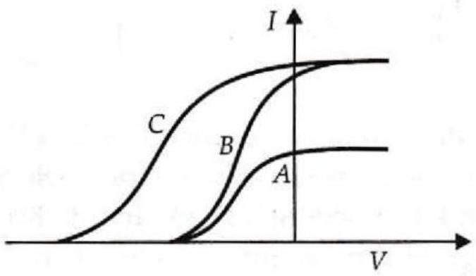
Hints: Saturation current ∝ intensity; stopping potential \(V_0\) depends only on photon frequency. Match identical plateau heights for part (a) and identical \(-V_0\) intercepts for part (b).
Pitfall: Do not confuse a shift in \(V_0\) with an intensity change; slope similarity is irrelevant.
Learning check: Can you now read any photoelectric I–V plot to infer intensity or frequency?
Semiconductor Electronics – AC to DC Chain
Q22 (I) Block Diagram Analysis
Identify elements X and Y in the AC-to-DC chain, draw their output waveforms, and predict how the waveform changes if the transformer's centre-tap shifts toward D₁.
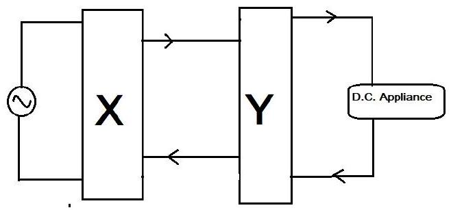
- X: full-wave rectifier (centre-tap type).
- Y: capacitor-input or choke-input filter reducing ripple.
- Centre-tap shift makes diode currents unequal ⇒ peaks of rectified output differ.
Common Mistakes
- Calling X the transformer instead of the rectifier.
- Assuming the filter removes ripple completely.
Current Electricity – Circular Network
Q31 (II) Wheatstone Variant
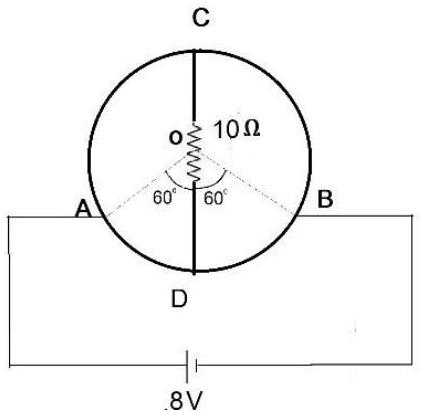
A uniform 12 Ω wire is bent into a circle. C and D are opposite points and joined by a 10 Ω resistor. An 8 V cell is connected between A and B (also diametrically opposite). Determine the current in arc AD.
Hints
- Circle → four equal arcs: each 3 Ω (Current Electricity concept).
- Equivalent Wheatstone: AC = AD = 3 Ω, CB = DB = 3 Ω, CD = 10 Ω.
- Bridge is balanced ⇒ no current in 10 Ω.
- Two 6 Ω paths A → B in parallel ⇒ \(R_{eq}=3\,\Omega\).
- Branch current \(I_{AD}= \frac{8\text{ V}}{6\;\Omega}=1.3\text{ A}\).
Common Mistakes
- Ignoring that resistance is uniform (3 Ω per quadrant).
- Placing the 10 Ω resistor incorrectly or assuming it always carries current.
Analytical Problem Solver
Electromagnetic Induction – AC Generator
Problem Statement
A coil of \( N \) turns, each of area \( A \), rotates with angular speed \( \omega \) in a uniform magnetic field \( B \). Explain the working principle of the AC generator and derive the instantaneous emf expression.
Given:
- Uniform field magnitude \( B \)
- Coil: \( N \) turns, area \( A \)
- Angular velocity \( \omega \); angle \( \theta = \omega t \)
To Find:
Instantaneous emf \( \varepsilon(t)= N A B \omega \sin \omega t \)
Solution Approaches
Flux-Differentiation (Faraday)
Write \( \Phi = B A \cos\theta \), then use \( \varepsilon=-N\,d\Phi/dt \).
Line-Integral (Motional emf)
Integrate \( \mathbf{v}\times\mathbf{B} \) along the two active sides.
Phasor View
Treat flux as a rotating vector; emf is its quadrature component.
Logical Breakdown
Magnetic Flux
Flux through coil: \( \Phi = B A \cos\theta \).
Time Variation
Angle changes uniformly: \( \theta = \omega t \).
Faraday’s Law
\( \varepsilon = -N\,d\Phi/dt \) gives induced emf.
Slip Rings
Maintain connection, deliver alternating output to load.
Step-by-Step Solution
Express Flux
Normal makes angle \( \theta=\omega t \) with \( \mathbf{B} \); hence \( \Phi = B A \cos\theta \).
Apply Faraday’s Law
Induced emf equals negative rate of change of flux for all turns.
Differentiate & Simplify
\( \frac{d\Phi}{dt}=-B A \omega \sin\omega t \). Magnitude:
Key Insights
-
Amplitude \( \varepsilon_0 = N A B \omega \) rises linearly with speed and field strength.
-
Derivative shifts cosine flux to sine emf, giving \( 90^\circ \) phase difference.
-
Slip-rings keep brushes in contact, delivering alternating polarity to the circuit.
Ray Optics – Prism Grazing Condition
Q27 (I) Right-Angled Prism
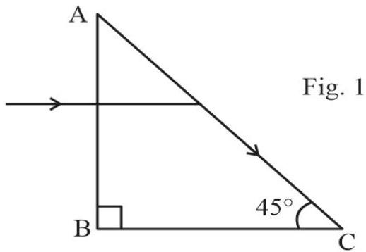
In the right-angled prism shown, the emergent ray just grazes face AC. Calculate the refractive index \(n\) of the prism material.
- Grazing emergence ⇒ refraction angle at AC \(r = 90^{\circ}\).
- Snell’s law: \(n \sin i = 1\).
- Geometry of right-angled prism gives \(i = 45^{\circ}\).
- Hence \(n = \frac{1}{\sin 45^{\circ}} = \sqrt{2}\).
- Ray Optics and Optical Instruments concept: link geometry to critical angle.
Common mistakes
- Using the incidence angle at AB instead of at AC.
- Calculator left in radian mode while entering degrees.
Atoms – Many Lines, One Electron
Q14 Assertion Discussion
Problem Statement
Hydrogen has only one electron, yet its emission spectrum shows many sharp lines. Using the Bohr model, explain this.
Given:
- Single-electron atom (H).
- Electron can be excited to orbits \(n = 2,3,4,\ldots\).
- De-excitation emits photons defined by Bohr formula.
To Find:
Cause of multiple spectral lines from a lone electron.
Solution Approaches
Energy-Level Diagram
List all downward transitions between Bohr orbits and link each to a wavelength.
Series Grouping
Organise lines into Lyman, Balmer, Paschen… using common lower level \(n_f\).
Population Analysis
Consider many atoms with electrons initially in different excited states.
Logical Breakdown
1. Excitation
Collision or radiation lifts the electron to \(n_i>1\).
2. Transition Count
Each \(n_i\) has \(\frac{(n_i-1)(n_i)}{2}\) possible downward jumps.
3. Photon Energy
Wavelength obeys \( \frac{1}{\lambda}=R\!\left(\frac{1}{n_f^2}-\frac{1}{n_i^2}\right) \).
4. Superposition
Ensemble of atoms emits all allowed wavelengths, forming a line spectrum.
Step-by-Step Solution
Sketch Energy Levels
Draw Bohr orbits \(n=1\) to \(n=5\) for a hydrogen atom.
List All Downward Jumps
From each excited level \(n_i\) enumerate every \(n_f<n_i\).
Calculate Wavelengths
Insert each \(n_i,n_f\) into the Bohr formula to obtain distinct \(\lambda\).
Key Insights
-
Multiple lines arise from multiple level pairs, not multiple electrons.
-
Every atom emits only one photon at a time; many atoms build the spectrum.
-
Bohr model of atoms fully explains hydrogen’s line series.
Key Take-aways
Formula Focus
Memorise core formulas and units; write them first to anchor the solution.
Concept First
Recall underlying principle before plugging numbers; prevents blind formula hunting.
Time Map
Plan: 45 min Section A, 35 min Sections B & C, last 25 min for review.
Smart Calculations
Round intermediate values wisely; use scientific notation to cut calculator keystrokes.
Neat Diagrams
Draw neat, labelled diagrams of rays, fields, or circuits; fetches instant method marks.
Final Check
Re-read answers, verify units and significant figures; avoid careless losses.